DrayTek 3300 to Watchguard Firebox 10.2 Core X VPN
To configure the Firebox we are using the 10.2 manager but the 11 series are very similar so you should be able to find your way round from these instructions. These instructions are based on using the configuration software rather than the web page as this example is an X550e system that does not support the web interface.
Firstly you will need to login to your Firebox using the username and start your policy manager.
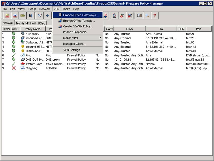
From the VPN menu at the top, select Branch Office Gateways as below:
You will be presented with the BOVPN gateways box:
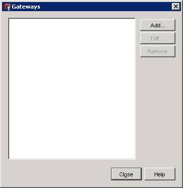
Click add and fill in your details which are discussed below:
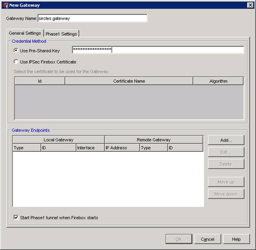
Firstly give your gateway a name at the top of the page - I usually find that the location of the gateway is the most sensible option but for this example I am sticking to generic terms for the sake of security.
If you are using a pre-shared key then you enter it as clear test in the user pre-shared key box.
To add the gateway endpoints, click Add under the endpoints section at the bottom of the page:
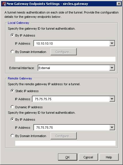
in the above we can see that our local gateway is 10.10.10.10 which is the local IP address of the firebox in this example. This simply refers to the internal address that you are using to access your Firebox. The external interface can remain as 'external' which is selected from the drop down list. If you are using a VPN trunk between different endpoints to offer redundancy in your VPN then you can set-up various host identities here but for now we are sticking to the simplest configuration.
Next we set the external IP of the DrayTek. The static IP address has been set as 75.75.75.75 as the DrayTek 3300 we are connecting to lives on ethernet fibre and has a static IP. The identity has been left as the same as the DrayTek will automatically use it's external IP as it's identity so this keeps things simple.
Once you have entered these then press OK to return to the last page.
Once there, click on the Phase 1 Settings tab:
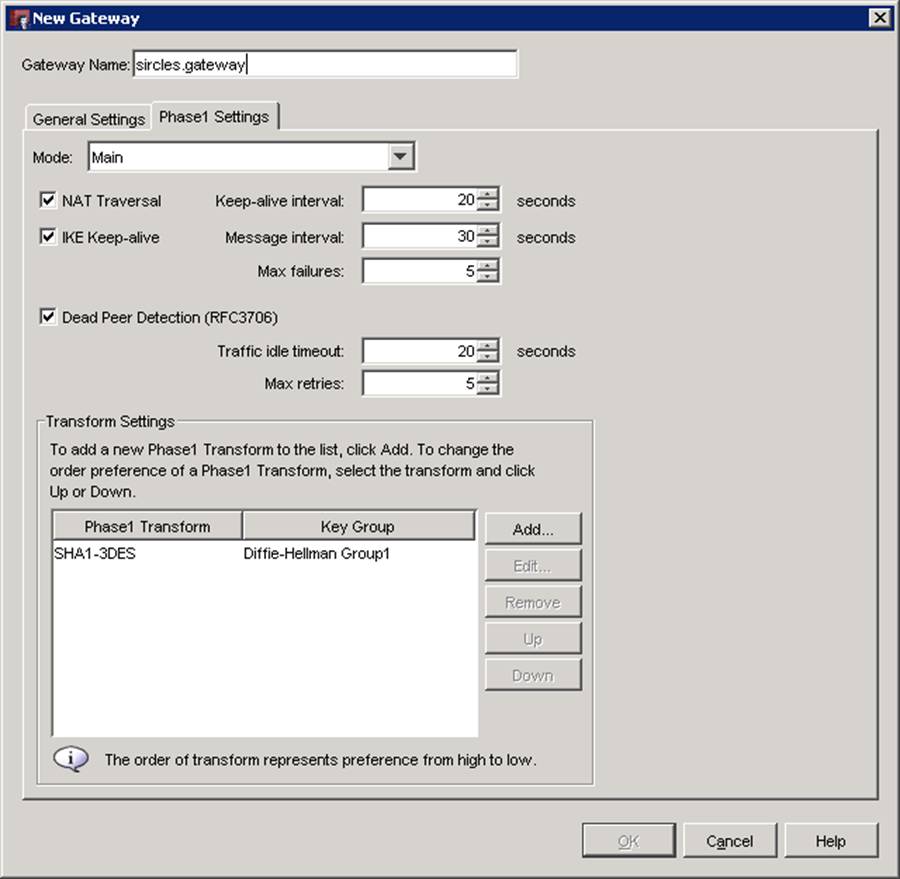
Above is the dialog for configuring the Phase 1 Settings. This is the first term of key exchange for your firewalls and we can see that the firebox already has various settings as a default. In this example most of these settings can be left as they and the actual important parts are the Mode and the Transform Settings at the bottom. We can see that the mode is set to Main which is our preferred option in this example and so we will leave this be.
The Transform Settings need to be updated so select the phase1 transform and click edit.
You should see a box resembling the below:
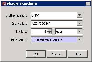
In our example - as the DrayTek supports AES 256 Group 5 - we are going to select SHA1 as our authentication and AES 256-bit as our encryption and use an 8 hour SA life but please feel free to choose any other SA length as the above settings are too simple to guess. These settings must mirror the DrayTek though so please make a careful note of what you decide upon.
Once you have entered your chosen settings, close the tunnel dialog box, and then click OK on the remaining dialogs to return you the Policy Manager
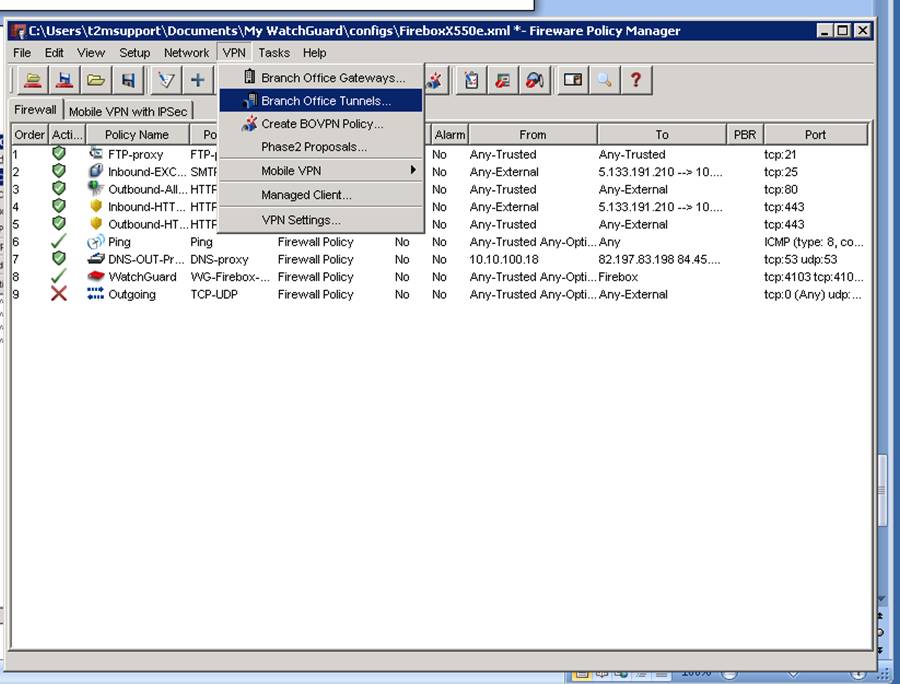
Now select the Branch Office Tunnels item on the VPN menu:
You will see the New Tunnel Dialog:
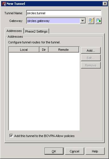
Give your tunnel a name and associate with your gateway under the Gateway selector as above.
Click Add to choose the addresses associated with your new tunnel:
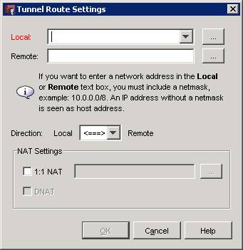
Choose your local network for the Firebox by either selecting it from the dropdown menu or by entering it manually. In this example the Firebox is on a 100.100.100.0/24 network:
Click OK to add your subnet and leave the other settings be as the defaults will suffice for this connection.
Click the Phase 2 Settings tab on the previous screen:
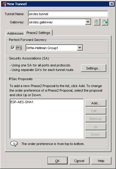
In our example our system is going to use perfect forward secrets and so PFS can remain ticked. We are going to use Diffie-Hellman Group 5 and so select that from the drop down.
The ESP-AES-SHA1 option chosen is already correct but be sure to click edit and check that you have a record of the SA time-outs as they will need to match the DrayTek. Once you are satisfied you can click OK and create your tunnel:
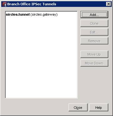
Click close to complete creating the tunnel.
The firebox configuration is now complete so save the settings to your firebox when you are ready. Now we will consider the DrayTek 3300:
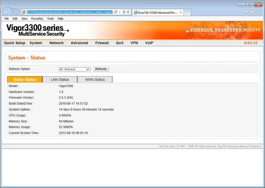
Log into your DrayTek 3300 as below:
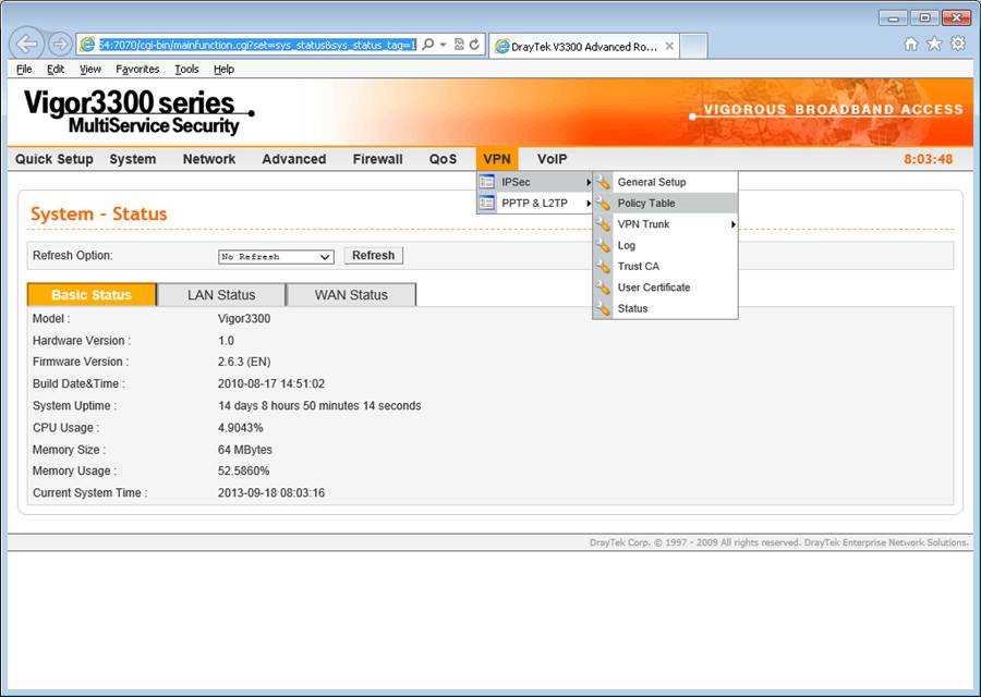
Under the VPN menu select IPSec and then Policy Table:
Under the new IPSec VPN make sure your VPN is set to enable or always-on depending on how you wish your VPN to behave. In this example we will select enable which will come up as soon as you need it in most cases.
Give your VPN a name and replicate the pre-shared key from the Firebox.
ESP is your security protocol so no need to change this.
NAT Traversal should be enabled. If you are connecting two Windows networks then NetBIOS can be enabled for Windows management traffic and machine location - such as computer browser service and the like - to function fully.
The WAN interface I am using is WAN1 and so this remains the same and the DrayTek local LAN settings of 100.100.100.0/24 go into the local gateway settings. Leaving the other settings as default simply means that the DrayTek will use it's LAN and WAN settings as it's ID for the VPN which is fine in this example.
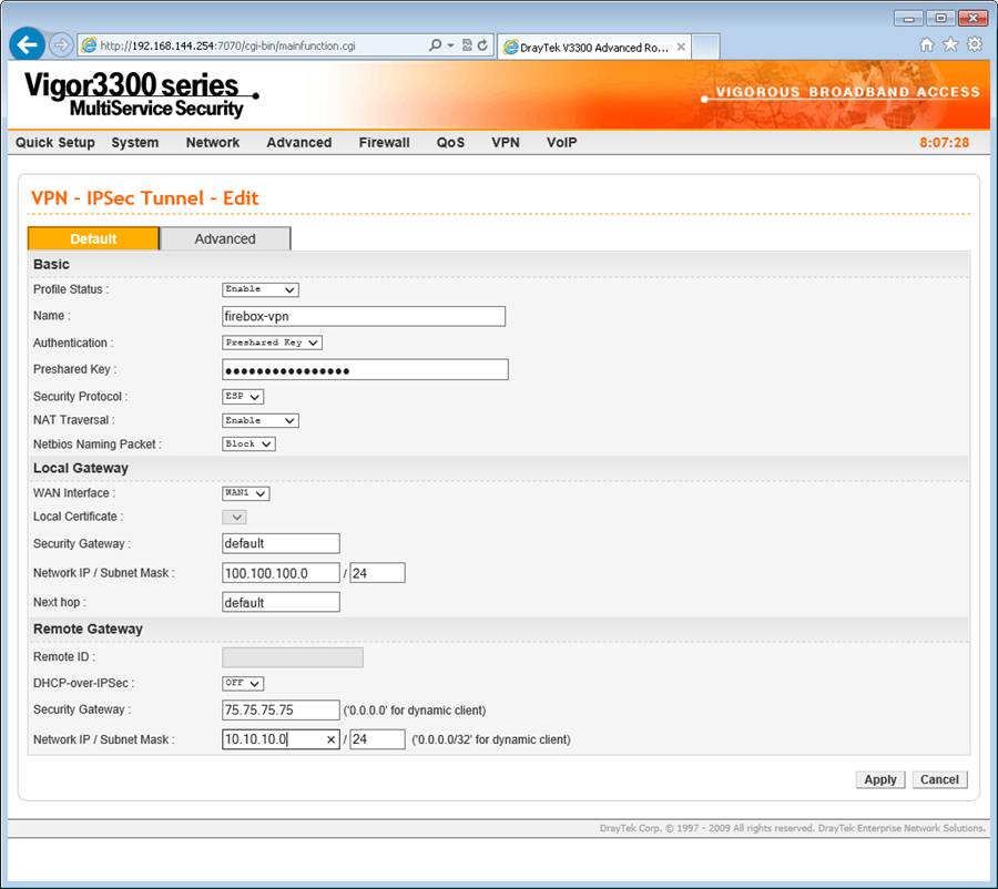
Under the remote gateway settings we add the external address of the Firebox and it's LAN address. This is the instruction to the DrayTek about encrypting traffic bound for a certain destination and what the traffic should be expecting when it arrives.
Once you have completed the above, click the advanced tab at the top of the page.
Now we configure the DrayTek phase 1 & 2 settings. On the Firebox we assigned an 8 hour AES 256-bit DH group 5 and so we complete the DrayTek in the same way as below:
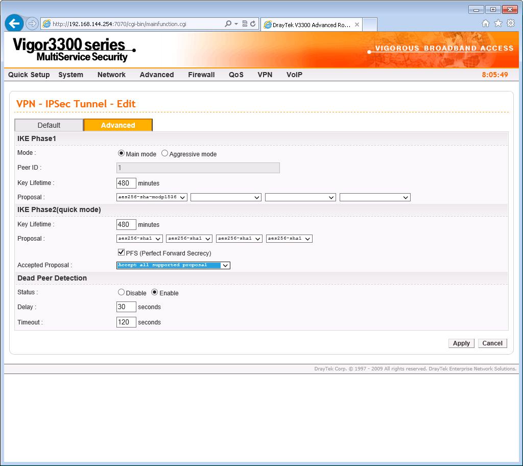
Once again we choose 'main' as the mode and tick the Perfect Forward Secret box for PFS to be enabled.
Say OK and you will see that the VPN is now set.
You can monitor under VPN IPsec Status and see the VPN comes up when you ping something on the other internal LAN:
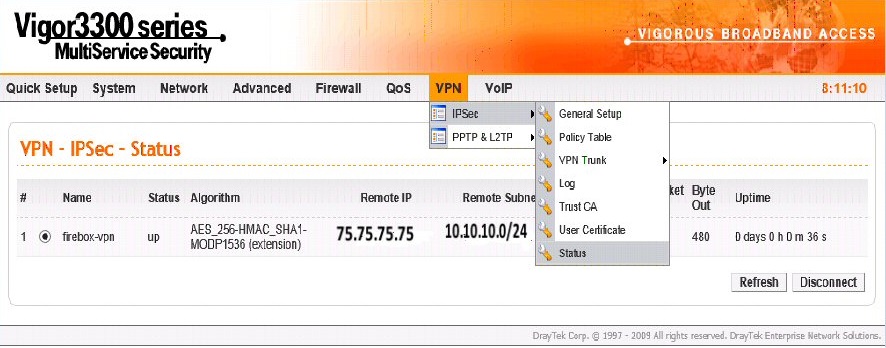
The above shows the VPN has been picked up with the correct IP and LAN subnets ;)
Buy DrayTek Vigor Routers Online